Timm's BMW E31 8-Series - Using LED’s in the FTP Main Beams
Updated 2018 with new LED link and Video
It took a while but I got there in the end
There’s a good reason that BMW chose to use H3 bulbs in the FTP main beams - there’s so little room behind the reflectors that H1 bulbs
wouldn’t fit. That means trying to fit any kind of decent LED is nigh-on impossible. First of all, let’s quantify what a ‘decent LED’ isn’t - the
LED’s pictured below are most certainly NOT going to do the job:
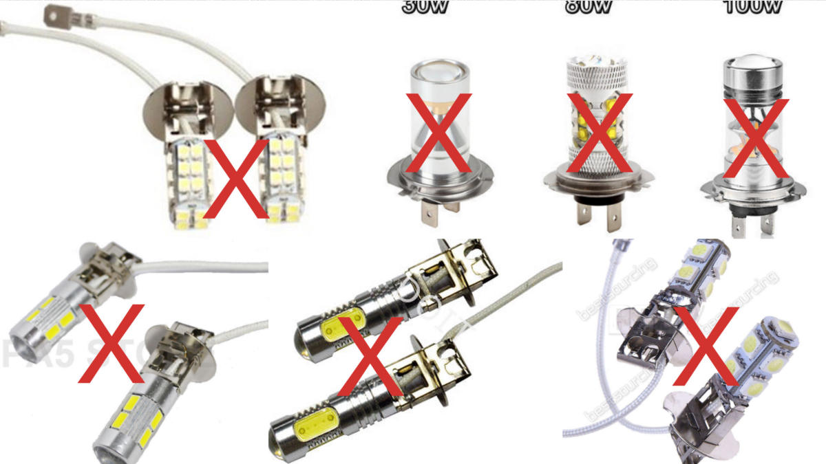
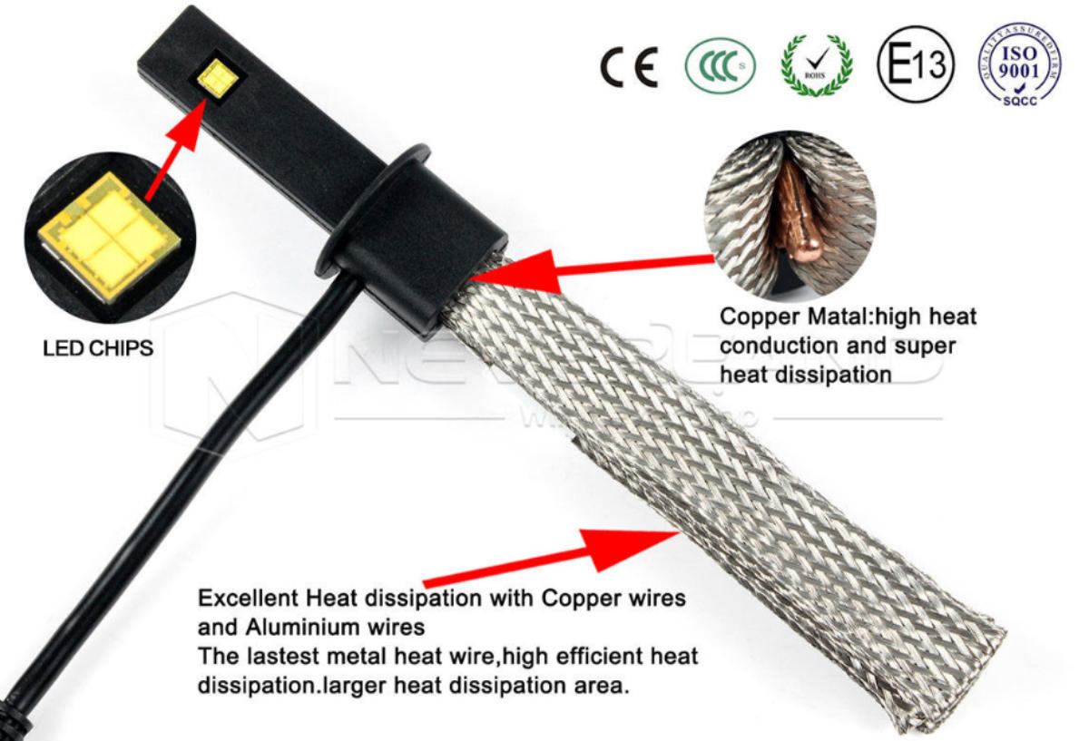

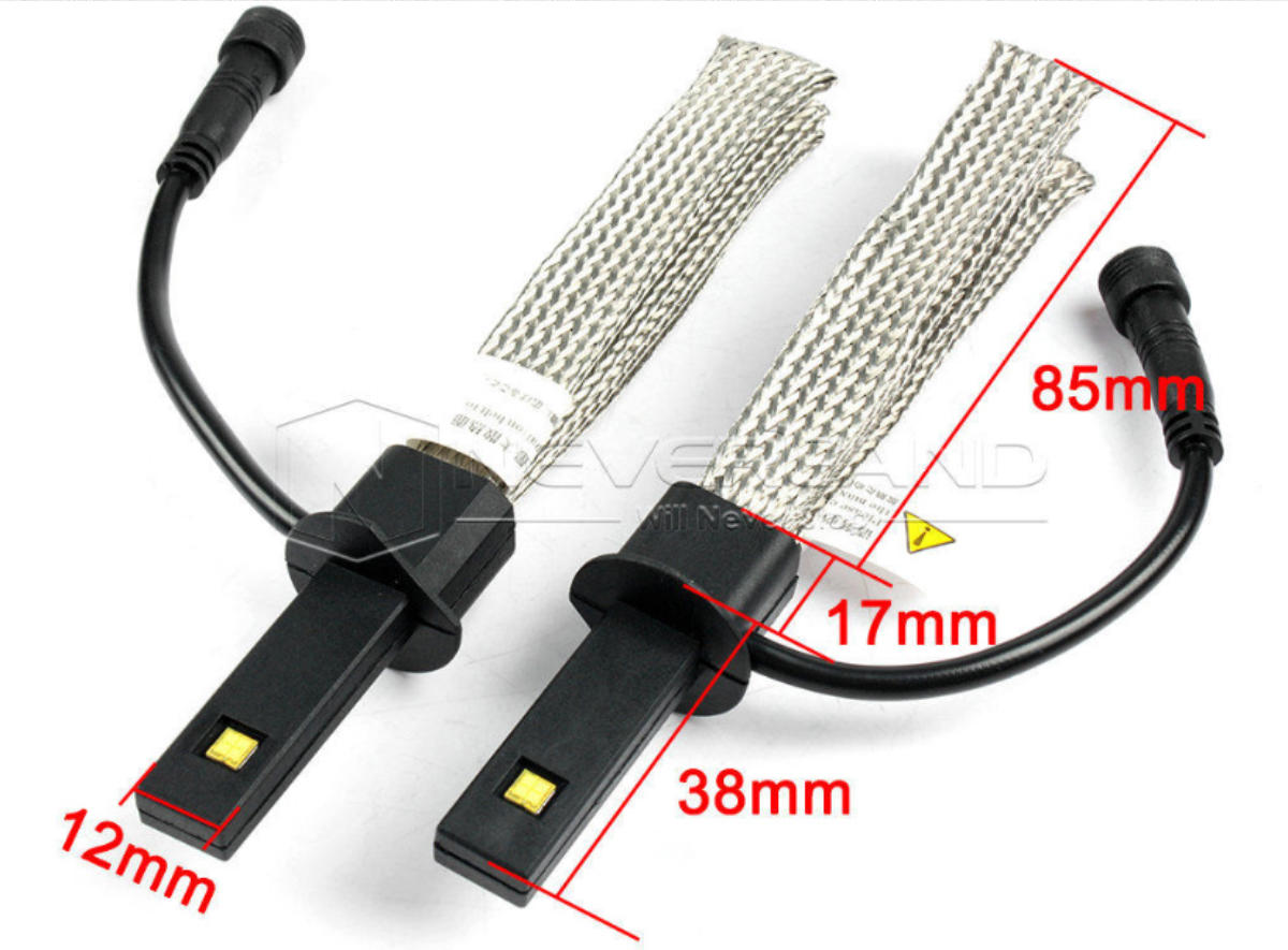
The LED unit above is one of the units that have a passive heatsink - the actual unit pictured above demands 1.2A (14.4W) and produces
around 1800 Lumen’s of light - a little better than a decent Halogen - so that will do nicely for our FTP’s. There are many units like this
available, but the one above is the only one that is going to fit without too much hassle, I’ve put up an Ebay link, but goodness knows how
long the link will remain active. The unit above is very short behind the mounting flange - measured at 17mm and importantly, the loom
enters the side of the unit rather than popping out of the top
Disclaimer: If you still have the original FTP’s (officially known as an Illumination Panels) fitted to your car, the plastic will be brittle and
parts are likely to break off starting with the mounting lugs - decide whether you want to risk this just for LED lights.
Start by removing the FTP’s from the car which is described here
The boring bit about why the LED’s above don’t work (unless you like driving in the dark)
The LED’s pictured above will not produce anywhere near enough light to take the place of a 55W Halogen (which produces around 1500
Lumen’s). All the LED’s shown above will produce a fraction of that amount (no matter what claims are made). No matter what LED’s are
fitted in the units above, they cannot dissipate the amount of heat that would be produced without a decent heatsink or a fan.
For physics enthusiasts - the most efficient LED’s produce 150 Lumen’s per Watt, reaching the dizzying heights of 8% efficiency. That means
that a 10W LED unit will produce over 9W of heat along with the very maximum of 1500 Lumen’s (but more likely close to 1000 Lumen’s).
So, don’t be bamboozled by the blurb that goes with these LED adverts, without a decent heatsink or fan, any LED producing 1500 Lumen’s
would melt in a few seconds. Halogen bulbs get rid of all their heat through radiation (you can feel the heat radiating in front of any Halogen
lamp) - LED’s don’t radiate heat, the heat needs to be conducted away from the LED slug and dissipated to the surrounding air.
If you want to know how much light the LED units above actually produce - measure the current demanded (with a multimeter) at 12V -
multiply that current (probably around 200mA) by the input voltage (12V) giving the Wattage (probably 2.4W) and then lets be generous
and multiply by 150 Lumen’s per Watt giving 360 Lumen’s - a little short of 1500 Lumen’s. An even quicker rule-of-thumb is to multiply the
current demand at 12V by 1500 to give a Lumen output
So, we need an LED unit that demands an Amp or so - and an LED that demands an Amp (12W) needs a way of getting rid of 11W of heat
That means we need a unit with a fan (won’t fit) or a passive heatsink (most don’t fit)
End of the boring bit - let’s get on with fitting one that does work
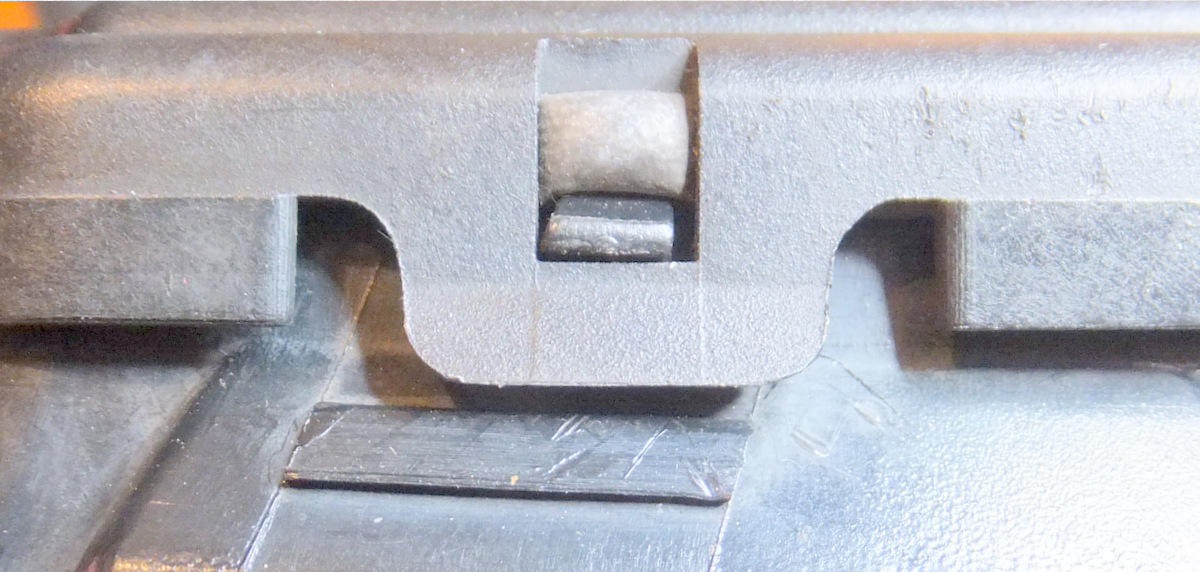
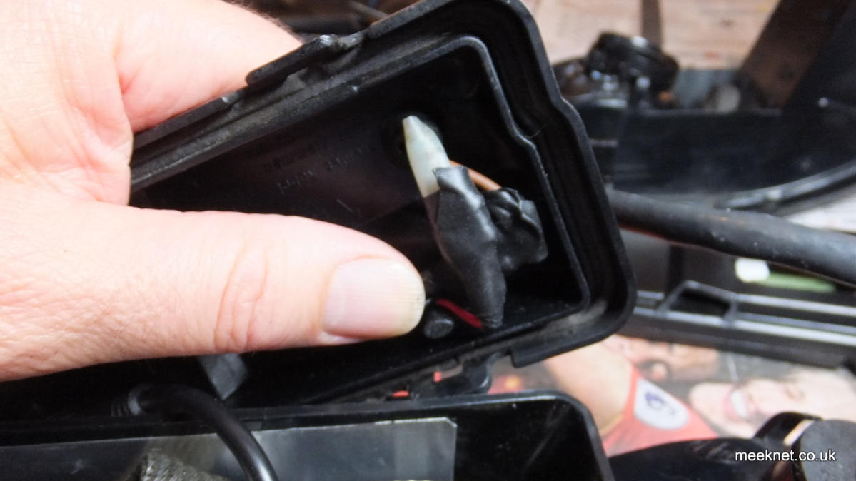
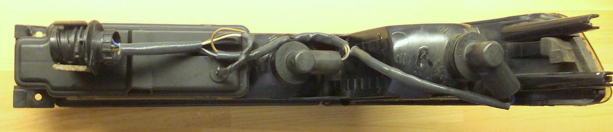
Remove the cover from the rear of the FTP by levering at the four points as seen below - carefully as the plastic may be brittle
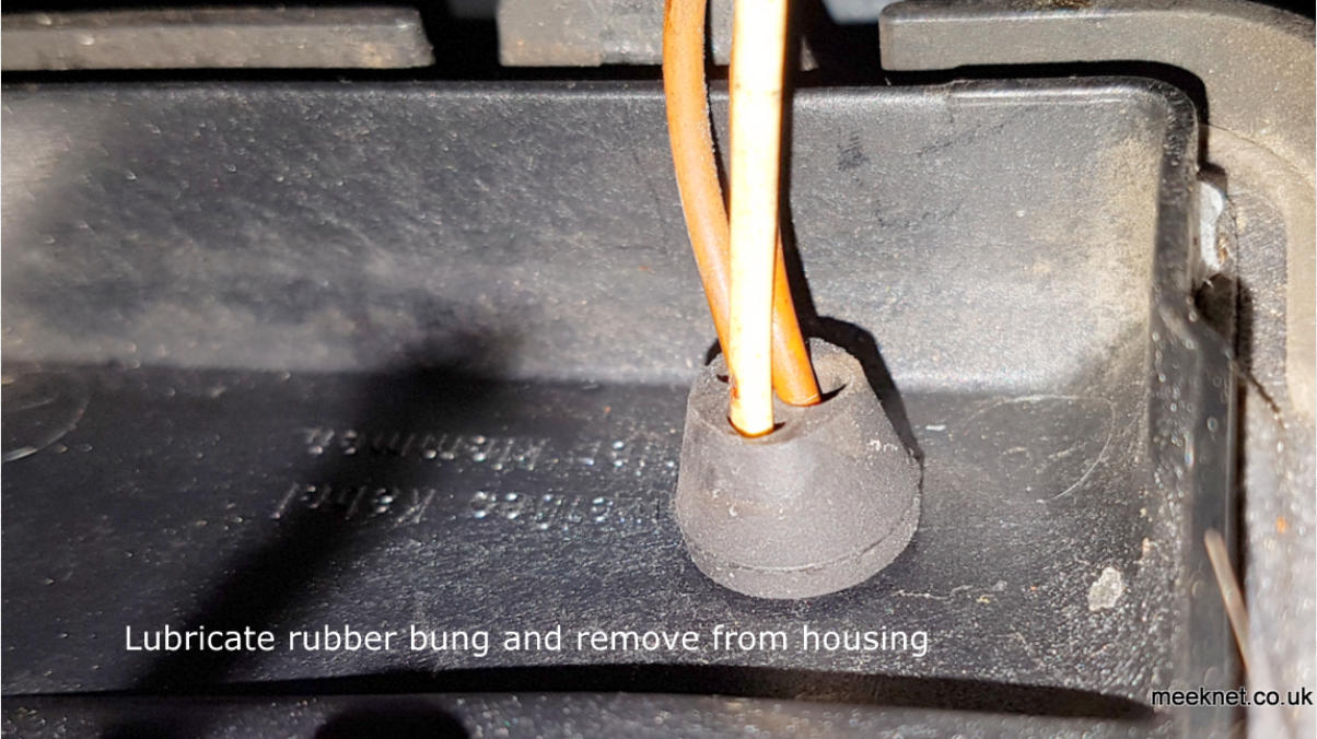
Disconnect the two female connectors from the bulb and bulb housing. It is easier to work on the cover with the wires removed - this is
quite easy if you use a little grease on the grommet, it will just pop out out - the female connectors just fit through the hole.
Fitting the current regulator to the rear cover
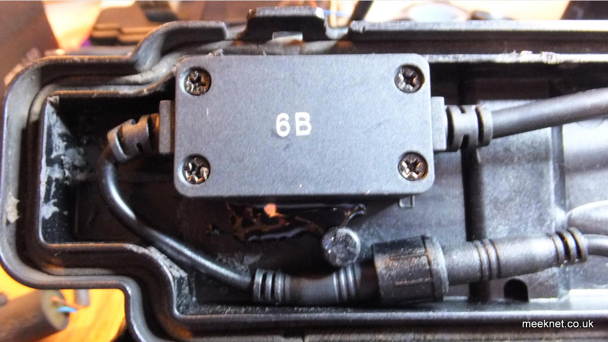
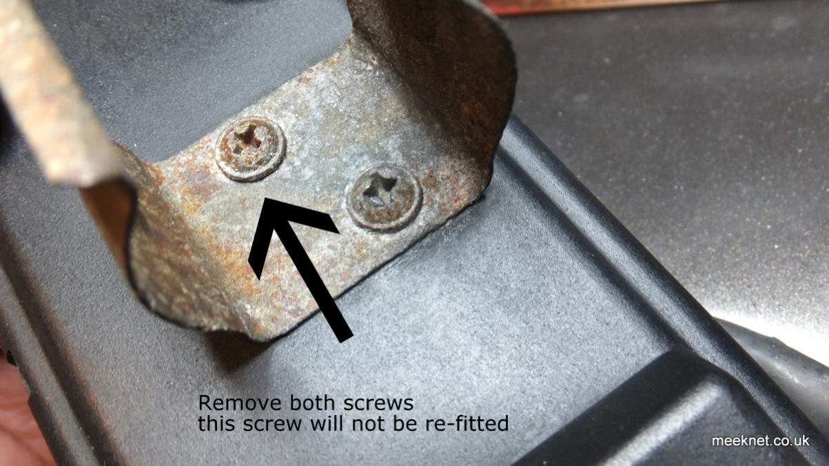
The LED comes with a small constant current regulator inside a small plastic box - we need to fit this to the inside of the rear cover - and to
do that we need to remove one of the pillars inside the cover (the one nearest the middle), these are here for the connector clamp
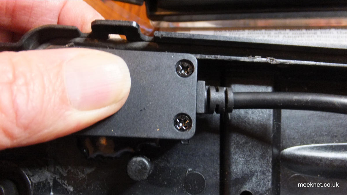
screws. Start by removing the clamp from the back of the cover:
Please note that some pictures are from the RHS rear cover and some are from the LHS rear cover -
these are mirror-images of each other and may cause some confusion!
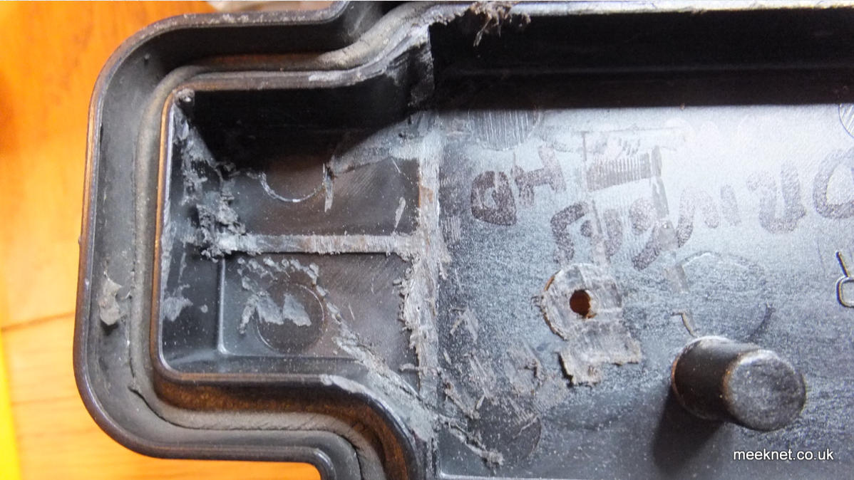
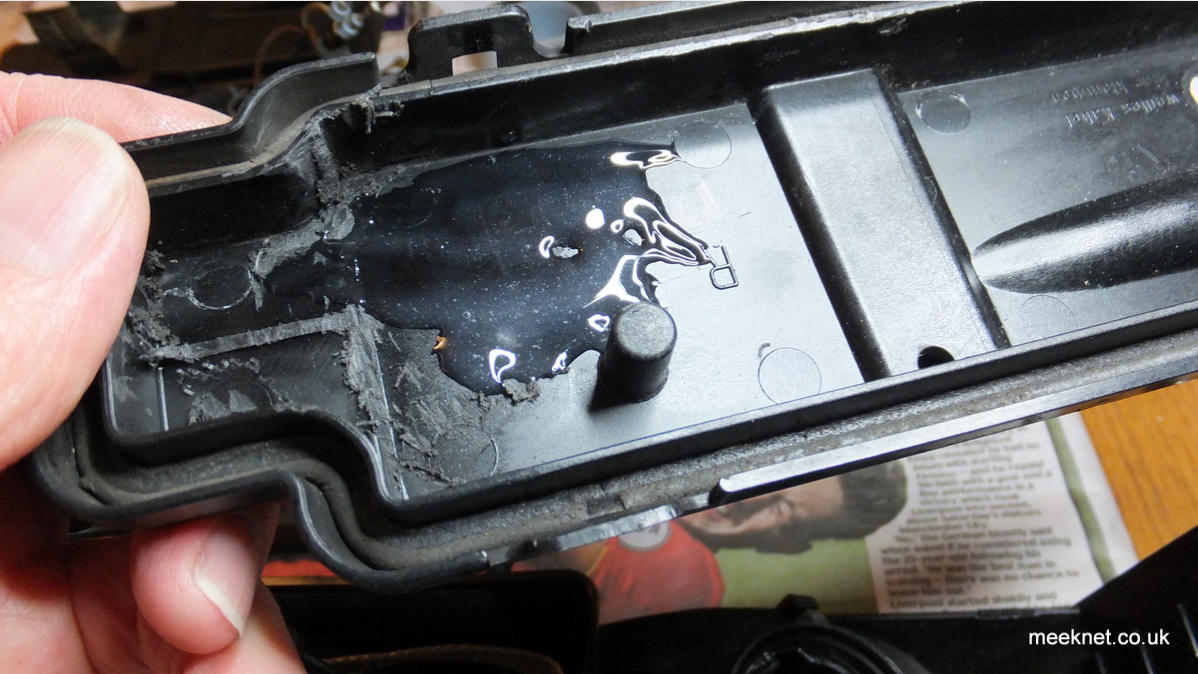
I removed the pillar using one of those oscillating saws (that boast lots and deliver little). We also need to remove some of the webbing
above the pillar. After all the sawing, the hole needs to be covered - I used Araldite Rapid

While we have the Araldite out we will glue the regulator to the rear cover as shown below - it fits quite neatly:
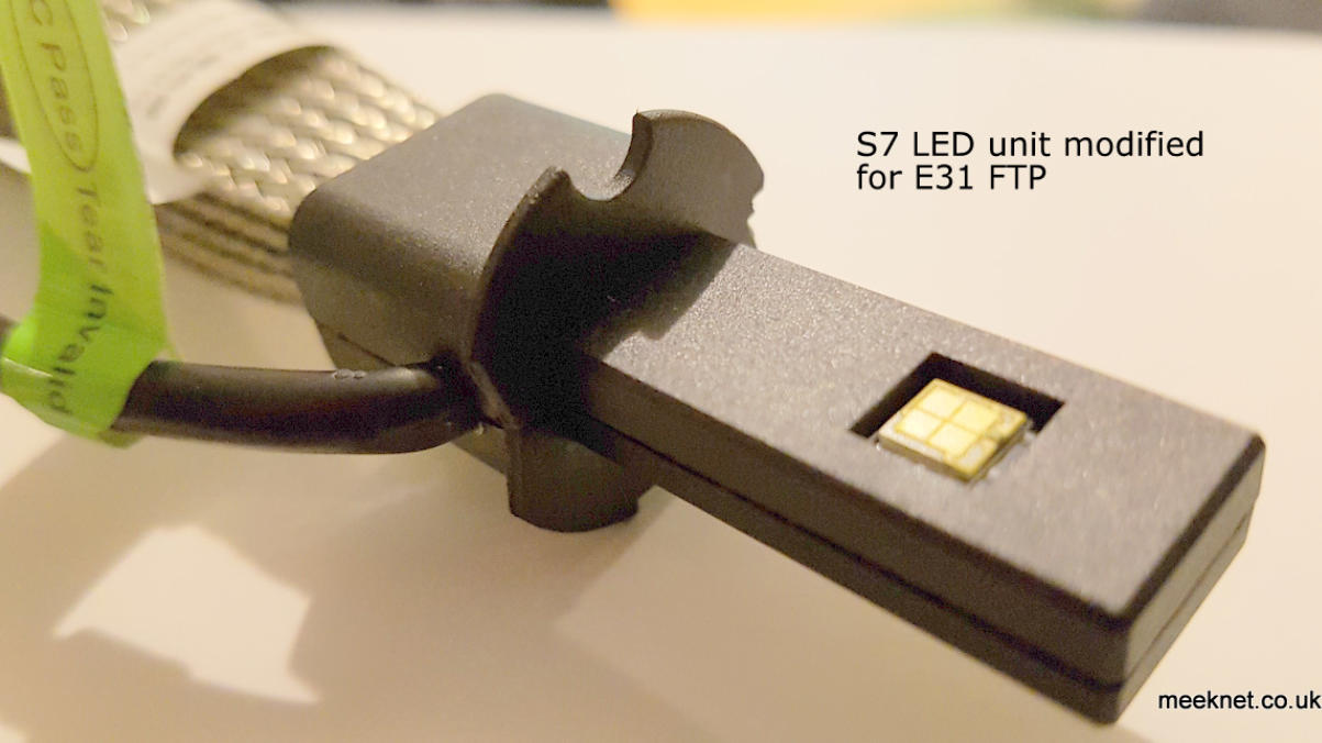
Fitting the LED Unit to the reflector
I did this twice - the first time I completed the job I got a light pattern that produced a small pool of light about a metre in front of the car,
and another pool of light that illuminated the tops of trees and nothing in-between. I was about to give up on the whole idea until I realised
that rotating the LED by 90-degrees the light might actually go somewhere useful. Instead of the LED’s facing up and down, we need them
to be left and right - so cut a couple of new cut-outs in the LED mounting:
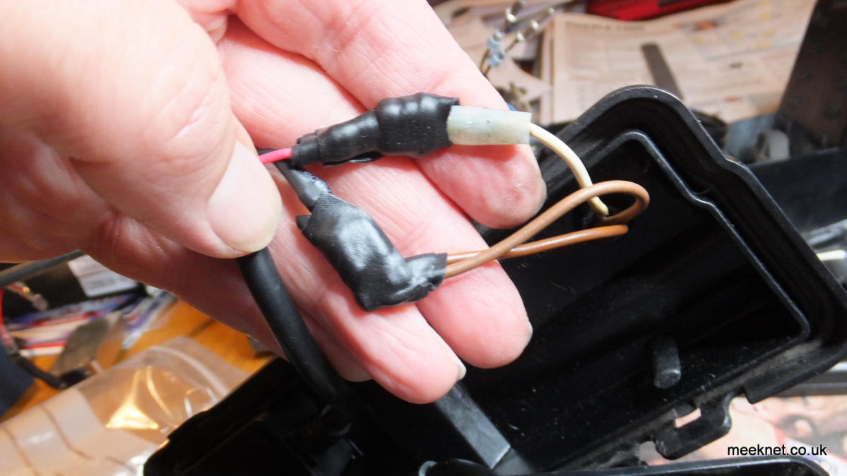
Pop the wiring grommet back into the cover and connect the wiring to the regulator - this could be done very neatly by snipping off the
connectors, soldering and heatshrinking - but, as the looms are over £200 a side I’m keeping them as they are! So, I’ve connected them
(after a bit of squishing to make a firm fit) and insulated them with self-amalgamating tape (not insulating tape as it will fall off):
I possibly could have made a neater job of that - but I was getting despondent at this point! We now fit the LED to the reflector 90 degrees
rotated so that the LED panels face left and right.
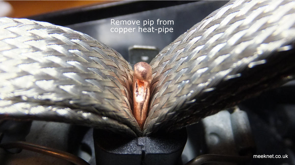
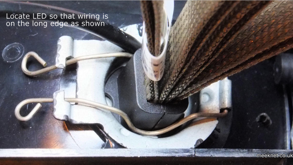
The lead to the LED gets in the way a bit and needs a sharp bend so that the retaining clip goes outside of the lead. The clip must press
down on the mounting and not on the lead. Spread the braid and snip off the round tip - we need all the space we can get:
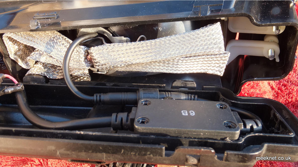
Now we have to spread out the braid to dissipate the heat - now, let’s be fair here, I have already spread the braid out when the LED was
90-degrees rotated and doing it ahain means it doesn’t look that pretty - well, that’s my excuse anyway. Spread the braid and mate the
connector pair:
Getting the braid out of the way of the wiring is important as you don’t want to put any pressure on the reflector as this will stop the ability
to adjust the beam-throw - take a bit of time to get it right and then re-fit the rear cover making sure there is no pressure behind it. Tidy
up the wiring where it leaves the FTP cover - I used self-amalgamating tape again:
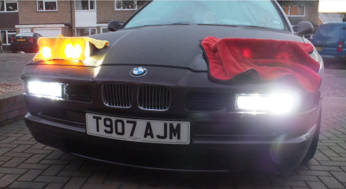
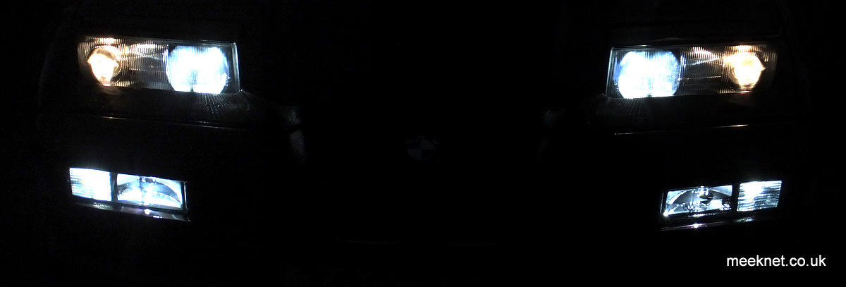
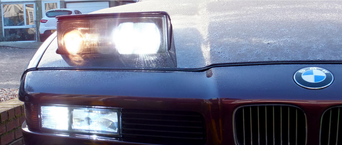
And that’s about it really, after refitting the FTP’s I covered the upper main-beams and adjusted the beam-throw - the FTP main-beams
obviously match the LED sidelights - and as I have fitted LED’s in the pop-up main beams they match too. But I wouldn’t fit LED’s to the
dipped-beams as the beam pattern is not tight enough and I would dazzle oncoming traffic even with the projector lenses. The beam
pattern in both main-beams is good - but there is a bit of light-spill as would be expected.

All done, Time for a Cup Of Tea