Timm's BMW E31 8-Series Headlight Adjustment and Aiming

As usual I broke something when fiddling - this time I managed to break the adjusters on one of the headlight pods when testing a new
batch of LED headlight units - the things I do for science! The headlight pods on a Euro model (I guess we can still call the UK models Euro
after Brexit) are very different to the USA versions. The Euro pods have two projectors (for fog and dipped beam) each side, a levelling
motor for the dipped beams, and more importantly for our purposes, a completely different adjustment system.
The adjusters on the Euro pods are designed with an advanced exploding plastic material - if you just look at them wrong they will fall apart
and the innards of the pod will bounce around the enclosure like a ferret in a shoebox. This information is quite important as a warning:
don’t touch the adjusters unless you really need to.
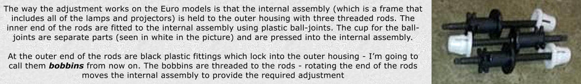
It is the bobbins that are made of exploding plastic and these fail with great abandon. In particular. they tend to snap in half so that they
pop out of the rear of the housing leaving the larger diameter part flopping around on the rod. The other failure mode is that the castellated
ends snap off and the rest of the bobbin disappears into the housing causing the internal assembly to flop around. Here is where the
bobbins pop out on the back of the housings:
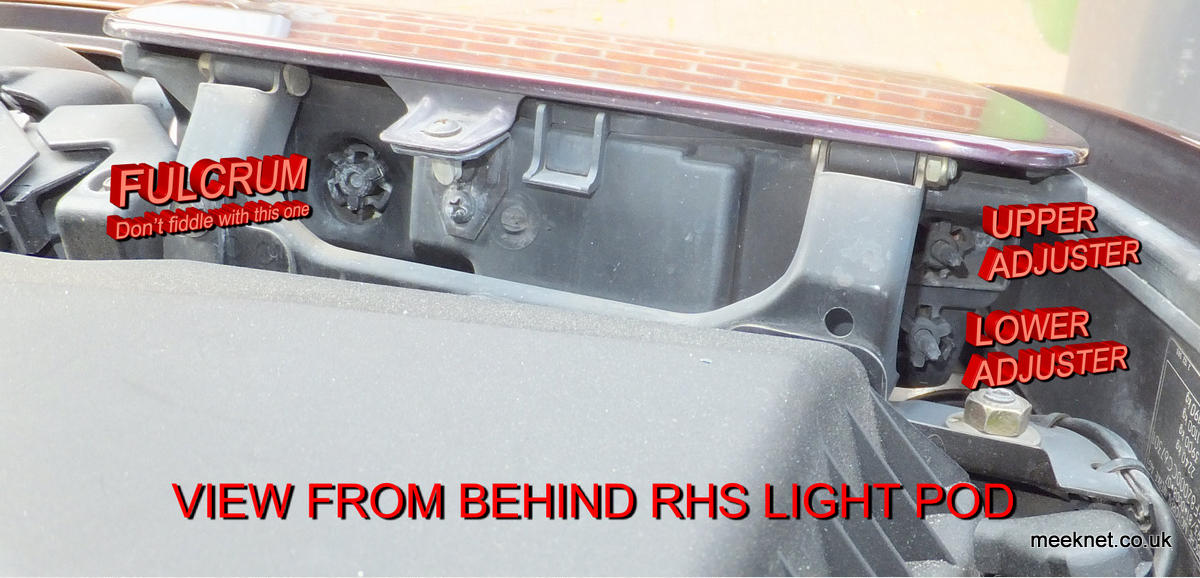
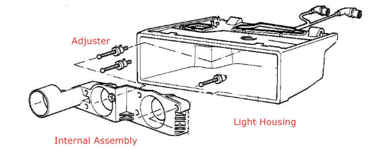
The picture above shows how the bobbins are fitted to the housing - they go through the housing and then are rotated into the locked
position to form a solid anchor for the adjusting rods. It is worth saying that the bobbin at the fulcrum point (as shown above) is NOT
threaded to the rod, in this case the bobbin is permanently fixed to the rod - well, until the bobbin self-destructs.
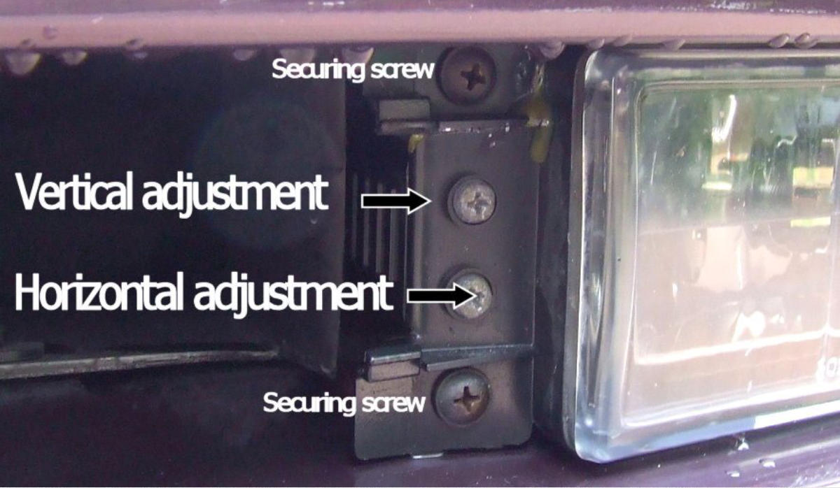
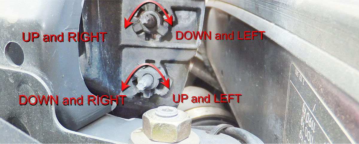
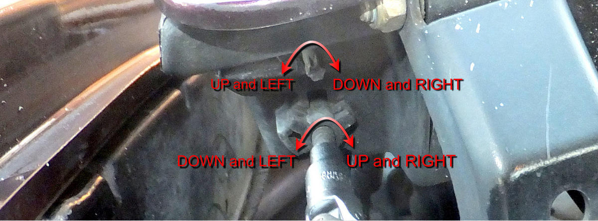
The adjustment of the internal assembly (and the aim of the lights) is made by turning the end of the rods which are formed into a male
Torx pattern. That all sounds pretty straightforward except that the two adjustable points are not directly assigned to left-right or up-down,
instead they work in concert to provide the correct adjustment.
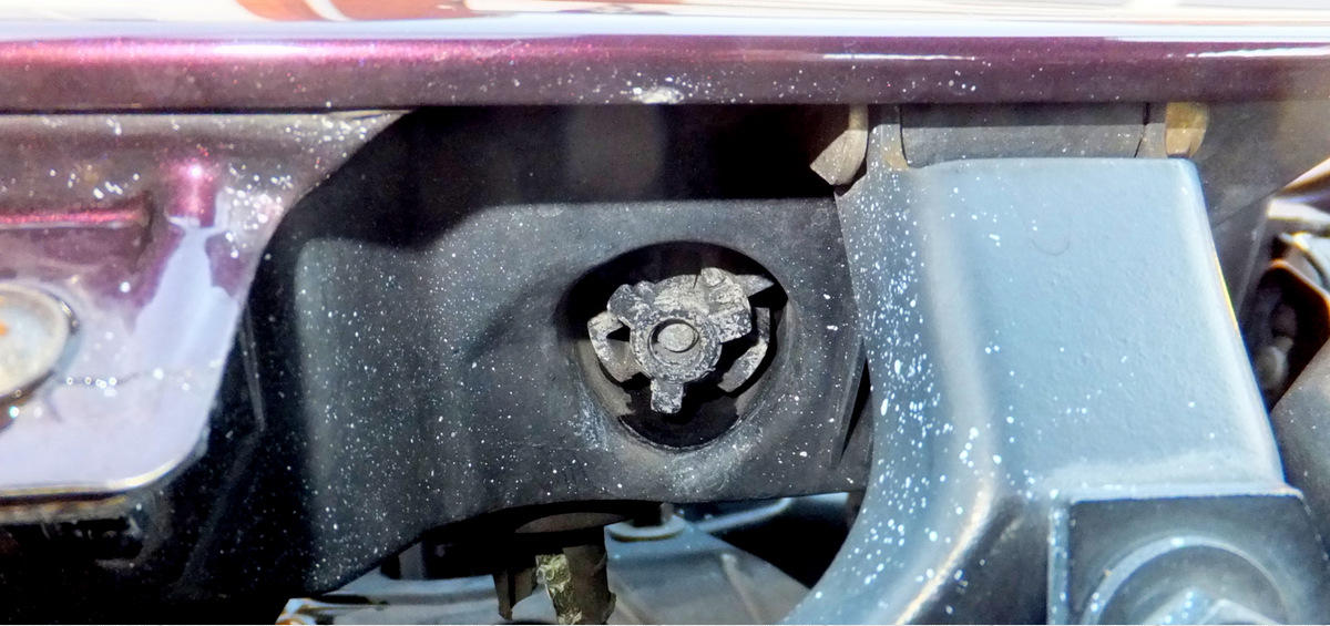
The picture above shows the fulcrum bobbin and also shows that there is no adjuster on the end of the rod. This bobbin can fall apart just
the same as those at the edge of the housing. In my car this is the part that disintegrated and allowed the rod to slide into the enclosure
which meant the light pointed to the right rather than ahead.
To fix this (probably permanently) I used a two-part epoxy to glue the rod back into the bobbin - and to glue the bobbin into the enclosure
as the arms had also dropped off. That was fine except that the aim was still miles out to left as I had pushed the rod too far into the
bobbin before gluing it all together. So, here is how to get the aim right.
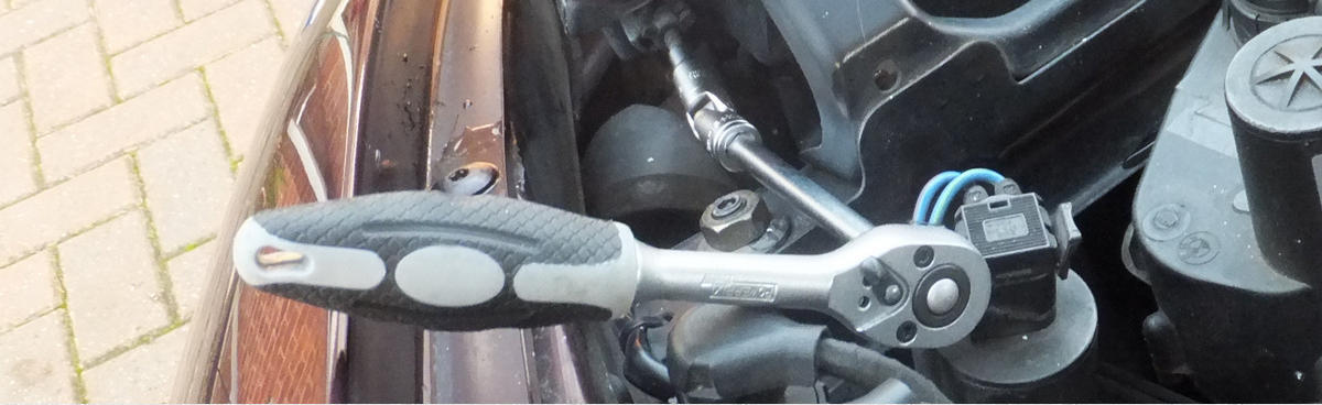
Above are the tools needed, a ratchet, a long extension, a universal joint and a female Torx socket
Here we go then, here is the view from behind the right-hand light. It’s a little fiddly getting the Torx socket on the end of the rods but not
too bad. The picture above shows which way to adjust each rod for the desired affect.
As the main beams give a less-focussed beam it is slightly harder to get right. The method of getting to these screws is
covered here.
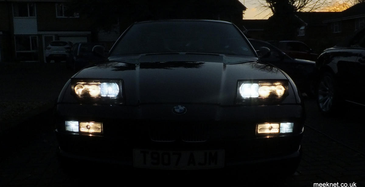
All done, time for a Cup Of Tea!
And here is the view from behind the left-hand light. Note that the adjustment direction is different between the two lights.
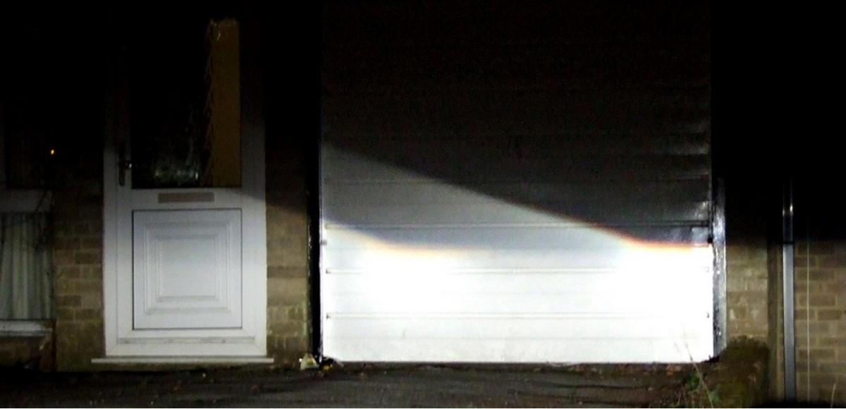
As long as one of the pods is aimed correctly, aiming the other one is pretty simple. The picture above shows the light thrown from the
dipped beams . The pattern above shows that there is a flat horizontal cut-off and a kick-up the the left on each beam.
Adjust the vertical position so that the horizontal cut-off is the same height as the ‘good’ light.
Get your tape measure out and measure the distance between the centre of the dipped-beam projector lenses from one pod to the other
(as far as I remember it is 137cm or so - but get this right). Adjust the horizontal position so that point where the kick-up occurs is
exactly the same distance as the measurement you took earlier - there is a tiny amount of convergence but we will ignore that!
And that’s it for the pop-up lights, as long as you haven’t fiddled with the internal assembly (each of the three lights on the internal
assembly can be adjusted separately, mess with that and it’s going to be difficult to get right again).
While we are fiddling with light aiming, I will include the adjustment for the FTP main-beams - in the UK these come on with the light-pod
main beams - in other world areas they just come on when the indicator stalk is pulled (which is where the acronym FTP comes from -
Flash To Pass), I know, it makes absolutely no sense at all.