Timm's BMW E63 and E64
Fitting a CTEK Battery Tender in the Boot
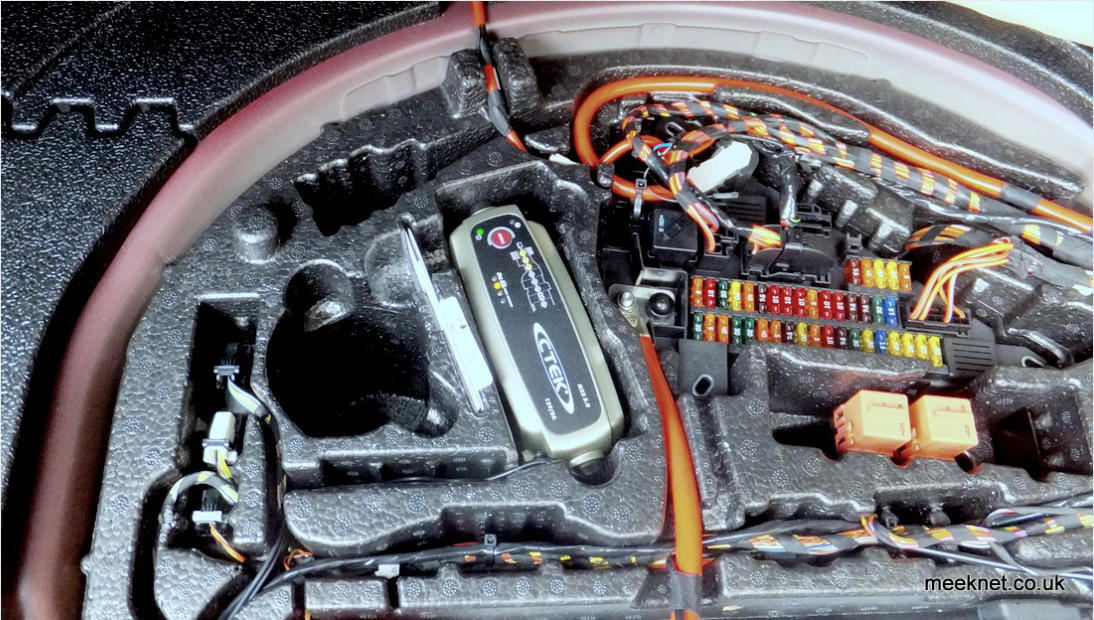
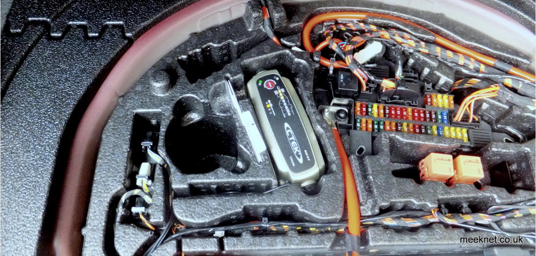
Just look at the picture below - it looks like it was made to fit in there!
We all know that you can’t charge the battery from the boot (trunk) because this bypasses the IBS (Intelligent Battery Sensor) and the IBS
will not ‘see’ the current being put into the battery - this might lead to over-charging the battery. BMW Says:
“Only charge the battery in the vehicle via the terminals in the engine compartment and with the engine turned off”
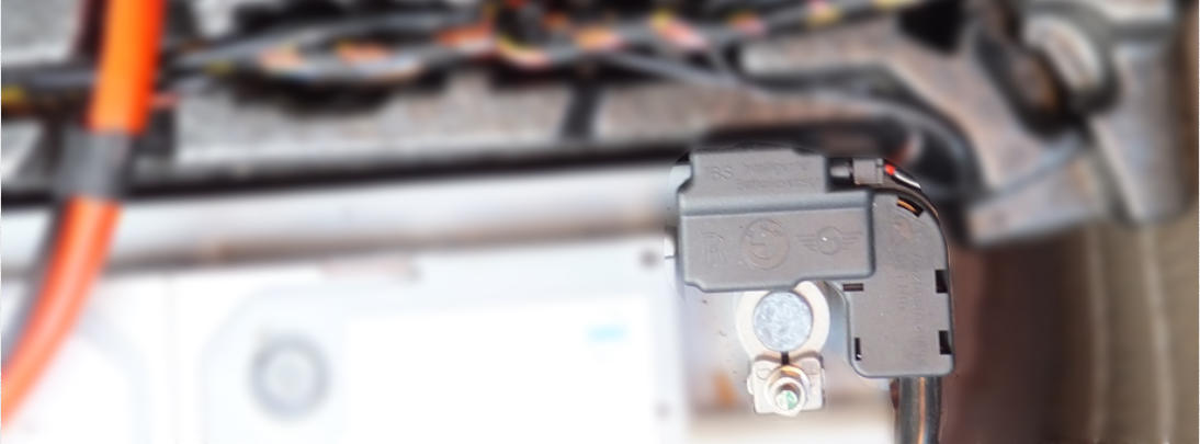
However, the IBS sensor is fitted in SERIES with the NEGATIVE battery terminal - actually bolted to the negative terminal itself. The IBS is
a mechatronic component, it serves as a mechanical fixture for the battery negative cable, and contains electronics to monitor the battery
temperature, current going in and out of the battery, and the voltage of the battery itself - it measures the voltage via a light-gauge wire to
the battery-positive distribution point. More info here.
So, how can you fit a battery tender in the boot when you must charge from the jump-start terminals in the engine bay?
Because the IBS is between the negative battery terminal and the negative cable that connects to the chassis - as long as the charger is
connected to the chassis (as it is in the engine bay) then the IBS can operate correctly and will measure the charging current. The
positive cable from the engine compartment is connected directly to the positive battery terminal - no current is measured in the positive
cable - only the voltage at the battery terminal and this is performed by the IBS.
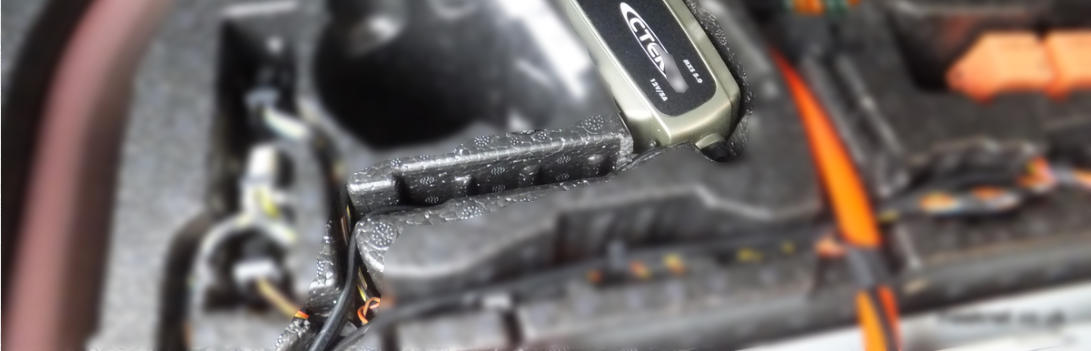
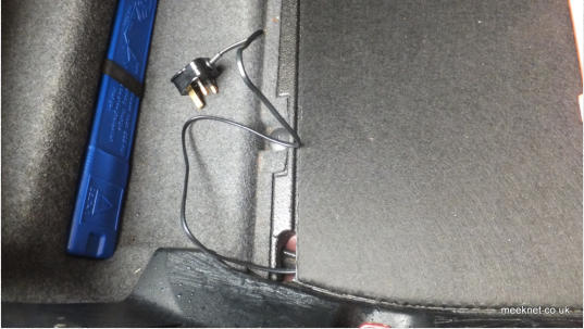
Enough blurb, here’s how it is done - I was intending just to site the charger behind the battery as there is a bit of room there - but looking
at the high-density foam that serves as a fuse box I saw a hole that looked just the right size:
Now, that looks just the right size - and it certainly is, the charger just fits in the hole, and fits so well that the charger is held tightly in
place. I’m sure on some models there is probably something in there, but there’s nothing in mine.
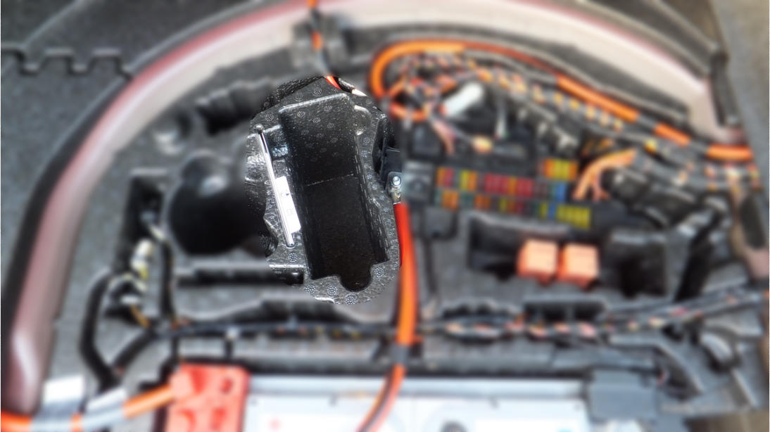
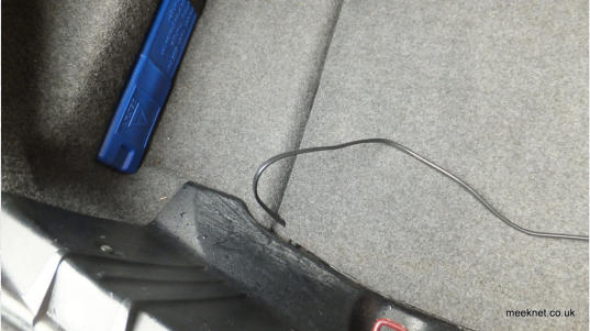
I made this up as I went along - but here’s the sensible way to do it - temporarily site the CTEK in the hole and then use a scalpel to cut a
channel into the cable route next to it:
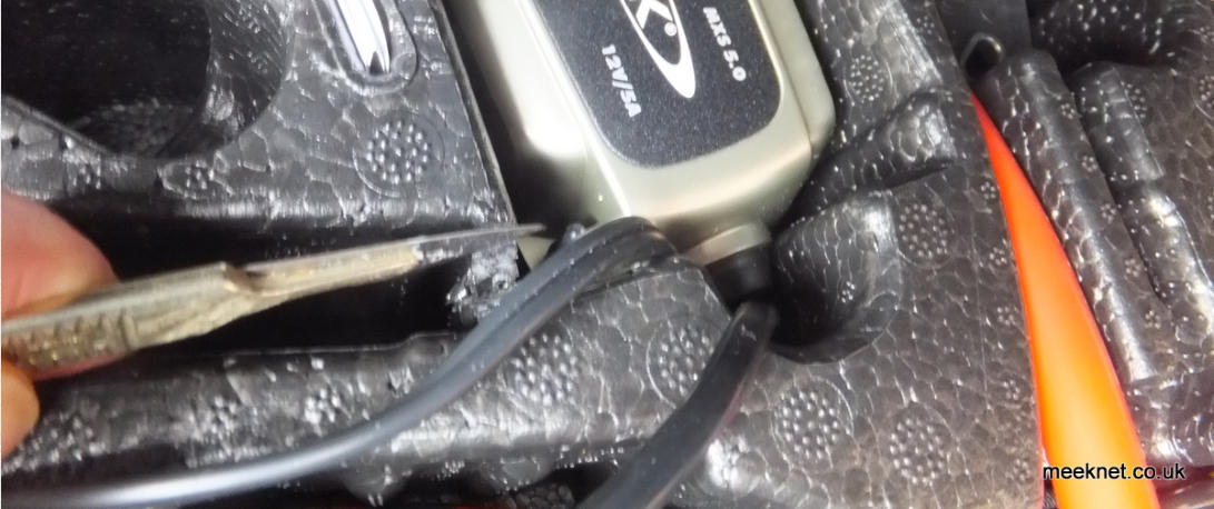
Both the mains lead and the DC output cable can now be routed via this channel towards the battery
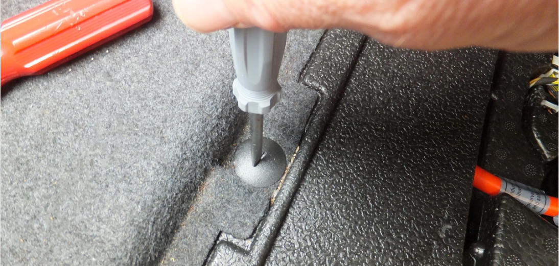
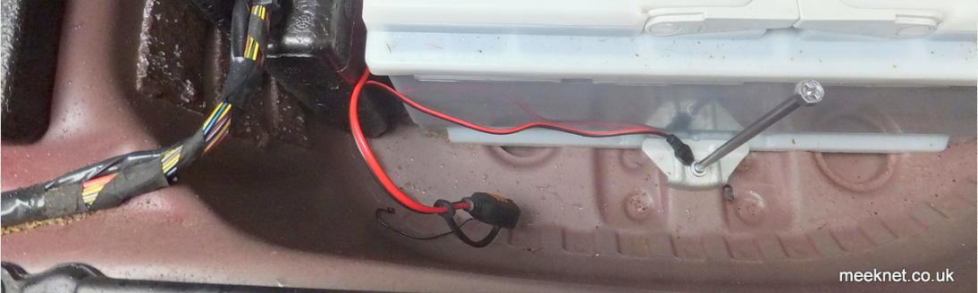
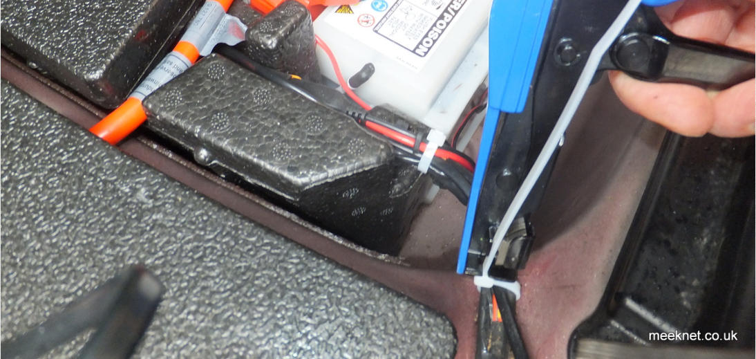
We need to get the cables past the positive battery cable - to do this we can lift up the cable enough to get the mains plug and the DC
connector through. Before the cable can be lifted, remove this fastener on the left-hand side of the boot:
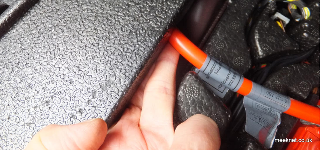
The positive cable is held in an open clamp at the edge of the boot under the high-density foam - this does not have to be removed, you
can lift the cable and it will lift out of the clamp far enough to get the cables and plugs underneath - push the cable down and it will go
back into the clamp nicely:
Now we can connect the charger output to the battery - we can connect the positive connection directly to the terminal. A great place to
site this is on the captive bolt that secures the positive assembly to the battery terminal. Tighten the bolt down until there is 3mm - 4mm
of thread available, slip the RED ring-terminal over over the thread and then fit a 6mm nut as shown below:
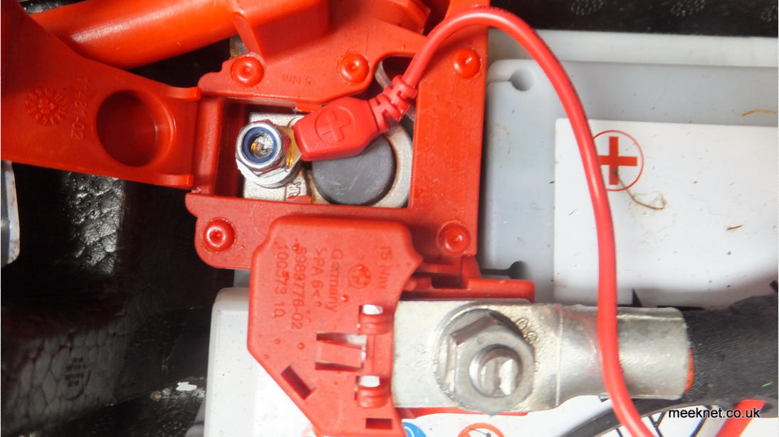
I snipped off the corner of the terminal cover to enable the lead to exit neatly - the cover can be clipped back down:
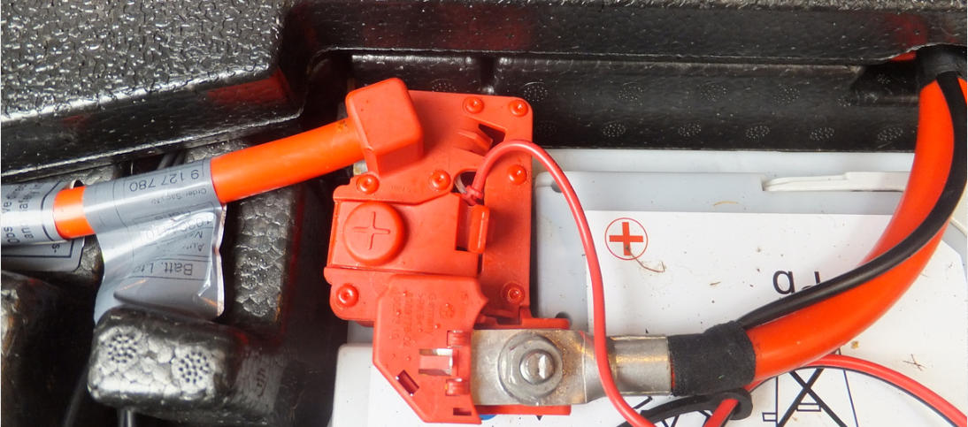
As earlier explained, the negative cable cannot be connected to the battery terminal, it must be connected to the chassis, and the
best and easiest place is on the battery hold-down here:

Remove the hold-down using a 10mm spanner and then remove the o-ring that holds the clamp captive on the long bolt:
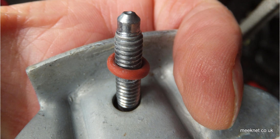
Bolt out, fit the negative ring over the end of the bolt, fit the clamp back on and the o-ring and then bolt back so the battery is clamped:
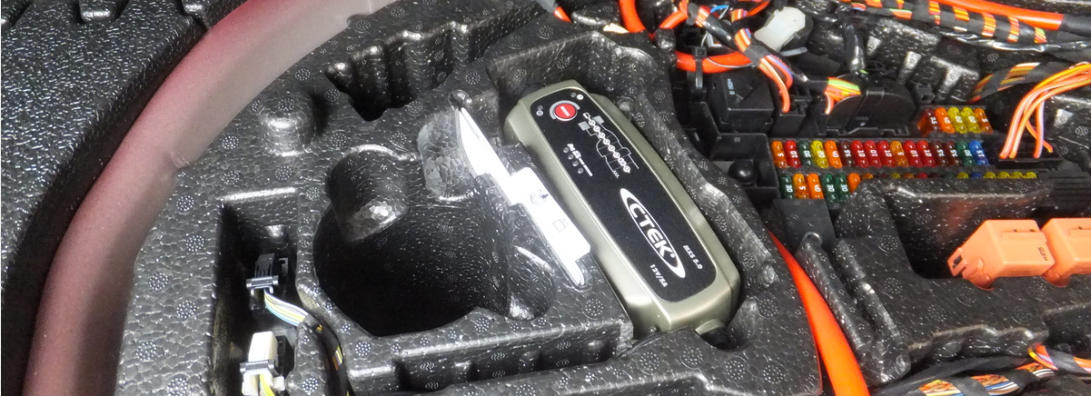
I’ve sited the charger connector pair just at the side of the battery as seen below - I then tidied up the cable run back to the charger and
put the excess cable under the charger where it is hidden. When everything looked tidy I pushed the charger further into the foam where it
fits snugly - that’s not going to move!
Final stage was to tie-wrap the cables into position neatly - the mains lead and plug can be routed neatly out of the compartment via the
left-hand side of the cover when needed, or stored behind the battery.
And that’s it - I quite like this one, much neater than the one in my 840ci - the only difference to my routine is that I reverse into the drive,
bung the extension lead in the boot, plug the mains plug in and shut the boot - as long as I remember to disconnect the extension lead
before I go out all will be fine.
All done, Time for a Cup Of Tea
Parts used in this article below
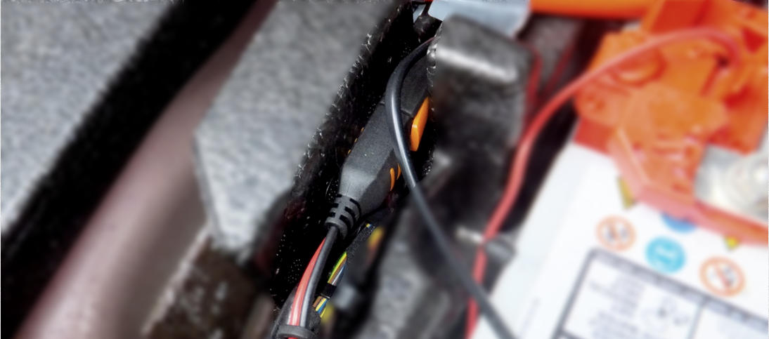
NOTE: The picture above shows the connector pair between the charger and the lead that goes to the battery. This caused a
bit of trouble about six months later. The problem was that the connector lock (shown in orange above) was being pressed
by the foam - and that partially separated the connector pair causing a partial loss of connection to the battery. This heated
up and damaged the socket which needed a quick squash before working again. I moved the connector pair further out to
stop this happening again - lesson learned!